Arduino Nano ESP32
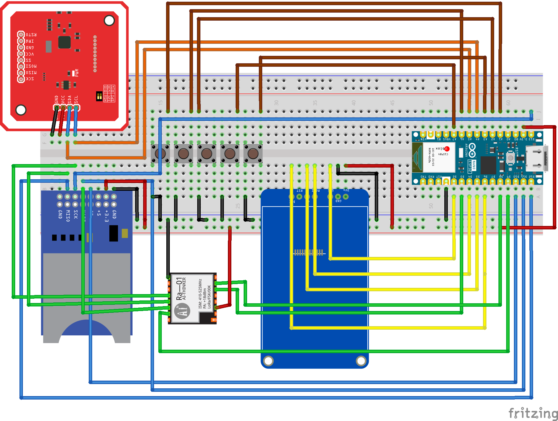
Here you can find breadboard scheme of CapibaraZero on Arduino Nano ESP32(photo is outdated):

And here the electrical diagram:

You can also download the original project here
Arduino Nano ESP32 pinout
With an Arduino Nano ESP32 board you must use the following pin if you doesn't want to modify source code:
SD card
For the SD card we must use the SPI bus.
- CS: pin D10
- MOSI: pin D11
- MISO: pin D12
- SCK: pin D13
SX1276
For the SX1276 we must use the SPI bus. We use the same pin of SD card but make sure to change CS pin since is the one that identify the devices on SPI bus.
We also need DIO 1 and DIO 2 pin to receive data from module in OOK/FSK mode. LoRa™ mode use SPI to get data.
- DIO1: pin D0
- NSS: pin D7
- DIO2: pin D1
- MOSI: pin D11
- MISO: pin D9
- SCK: pin D13
PN532
Make sure to put PN532 in I2C mode since we use it in this way. You can also use in UART mode or SPI mode but you need to change source code
- SCL: pin A6
- SDA: pin A7
Display
- SCL(SCLK): D4
- RST: Not connected
- SDA(MOSI): D2
- CS: pin D6
- DC: pin D5
- BLK: 3v3
IR
- Emitter: D3
- Receiver: D8
TP4057
- BAT+: A0
Buttons
- Right: pin A1
- Down: pin A2
- OK: pin A3
- Left: pin A4
- Up: pin A5